A nominal dimension in a CAD model is not a promise about the printed part. The slicer must represent that geometry with a particular nozzle, line width, layer height, wall generator, flow, material, and machine profile. Decide first whether the feature is a wall, a gap, a hole, a pin, a bridge, or an unsupported island; then inspect the generated path for that feature rather than applying one minimum feature chart to every setup.
Measure and classify the feature
Record the intended wall, gap, hole, pin, or mating clearance, its orientation, and whether it is internal or external. A slicer measurement tool can compare points, edges, and faces in the source model before slicing. It does not measure the printed part or establish the uncertainty of the mesh. For a fit-critical feature, keep the source measurement, the target fit, and the eventual physical measurement separate.
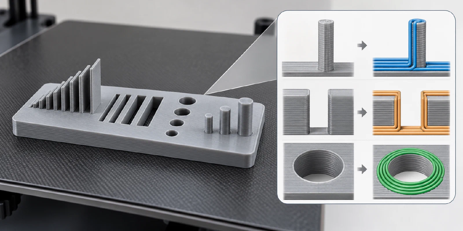
The nozzle sets the scale of XY path generation, while layer height mainly changes vertical resolution and time. PrusaSlicer guidance keeps layer height below roughly 80% of nozzle diameter as a general recommendation and rejects a value above the nozzle diameter; this is profile guidance, not a universal quality threshold. Changing nozzle, line width, or orientation can change whether a wall receives a perimeter, an adapted-width path, or no visible path at all.
Inspect the wall and gap generator
Arachne can adapt extrusion width around thin features. Other modes expose minimum wall width, minimum feature size, and minimum wall length. Depending on the active values, a feature can be widened, merged, closed, shortened, or skipped. PrusaSlicer’s thin-wall detection can create one perimeter around a small shell, but a wall narrower than one extrusion width may still be ignored. Read the exact release and active mode, then inspect the layer preview at the critical heights.
When a profile uses percentage widths or multiple nozzles, verify the resolved width for each selected tool after import or upgrade. PrusaSlicer 3.0.0-alpha11 documents a change to the basis for percentage widths and a shared layer-height requirement across selected extruders. Those are alpha- and product-specific profile rules, not dimensional guidance for another slicer or release. Inspect the effective values and resulting paths in the target build.
Also inspect nearby infill and skin paths. Version-specific controls can merge or discard small regions; Cura 5.14.0-alpha.0 release notes describe such alpha controls without giving a universal feature threshold. Geometry present in the model does not show which short paths remain in the slice.
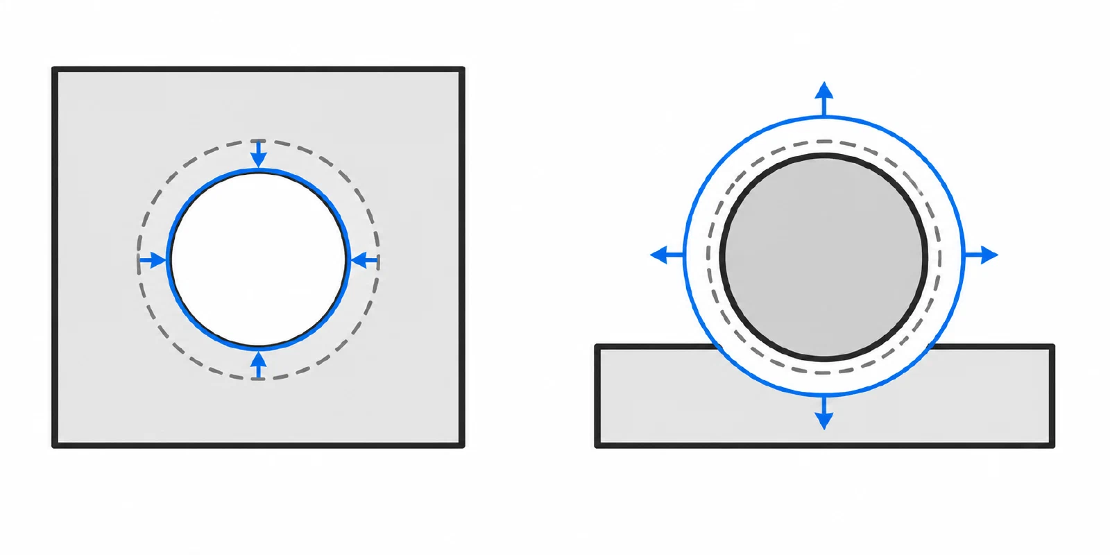
For bridges, use the bridge-specific preview and settings rather than assuming a wall rule applies. A bridge line width cannot exceed the nozzle diameter in the documented OrcaSlicer behavior. For holes and contours, X-Y compensation changes the path around the feature; slice-gap closing can fill small cracks while reducing resolution. Those controls change the planned toolpath and must be recorded with the preview.
For a counterbored hole, inspect any tool-specific bridge mode and check whether the intended opening remains in later layers. A partial or sacrificial bridge can change the path across the recess; the support guide covers those choices. Measure a printed sample before treating the opening as a fit.
Treat compensation as calibration, not correction by habit
Elephant-foot compensation changes the first-layer footprint to counter bed squish. A documented example around 0.2 mm with a default 0.4 mm nozzle is a starting example, not a universal clearance. Excessive compensation can weaken a brim connection or distort a thin-feature junction. Check the first layer and mating edge after changing it.
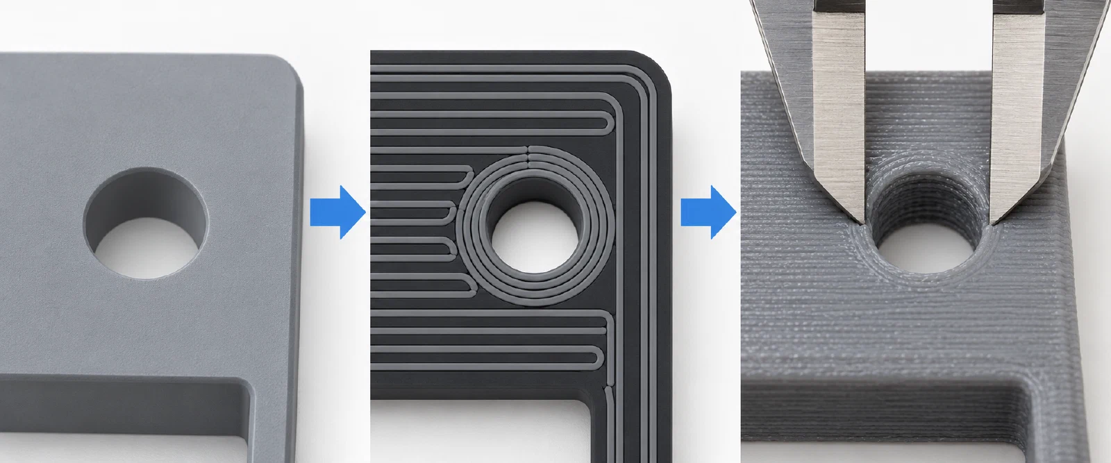
For functional fits, use a small coupon containing internal holes, external pins, wall steps, gaps, and the relevant orientation. A tolerance-calibration workflow can expose a sequence of nominal hole clearances and help tune XY compensation, but the result belongs to that printer, filament, process, and measurement method. Concave and convex features can respond differently, so do not use one measured surface to predict every feature on the final part. Record nozzle, material and dry state, layer height, line width, flow, temperature, cooling, slicer/version, compensation, measurement tool, and fit result.
A feature-survival workflow
- Measure the source feature and state the functional requirement.
- Identify nozzle, layer height, line width, wall generator, material, and orientation.
- Slice a small test or the part and zoom into the critical layers.
- Confirm the feature has the intended perimeter, gap, hole, bridge, or island path, including adjacent infill or skin where it affects the feature.
- Print a coupon when fit or strength matters; measure both internal and external features.
- Change one process or compensation variable, record the result, and do not transfer it to another printer or filament without validation.
There is no evidence here for a universal wall width, hole size, clearance, compensation, or dimensional tolerance. For orientation and load implications, see orientation for strength, surface, and reliability . For a complete file and preview check, use model repair and sliced-preview preflight .
Back to top ↑