A belt printer changes how the slicer relates model orientation, support direction, the moving belt, and machine coordinates. OrcaSlicer’s belt mode is specific to its supported build and printer profile. It does not make a generic belt profile a verified match for your machine.
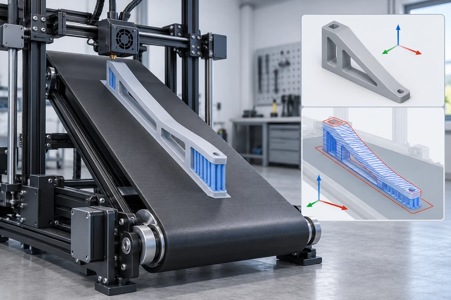
Confirm the build and machine profile
The OrcaSlicer documentation currently describes belt support as available in
nightly builds with the _belt suffix or releases later than 2.4.2. Check the
exact installed build and confirm that the intended profile enables belt mode
before relying on belt-specific controls. The documented profiles use a typical
45-degree machine as a starting configuration; that angle is not a universal
value.
Record the printer model and topology, firmware, profile source, slicer build, nozzle, material, and process. Verify the actual belt width, gantry clearance, tilt axis, and travel limits against the machine’s own documentation. If using a generic profile, enter only machine-specific dimensions and settings that you can verify. The slicer’s starter profile or a successful slice does not establish that the profile matches your printer.
Read the belt geometry in the right frame
In OrcaSlicer’s Prepare view, X runs across the belt, Y runs along it, and Z is height above it. The model is rotated for slicing, then toolpaths are transformed back and mapped into the machine frame. A belt profile may allow a part to extend beyond the displayed Y length, but this does not remove the belt-width or gantry- clearance constraints. Check the actual machine and intended print length as well as the slicer’s displayed area.
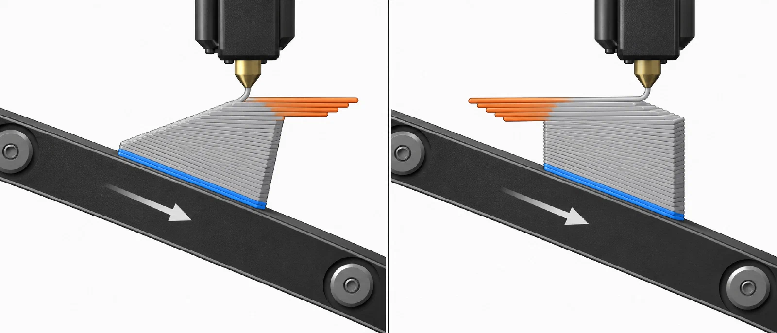
Belt orientation also changes what an overhang does. An overhang at the leading end of a part can begin in mid-air; one pointing back along the belt can be laid onto material already deposited. Compare candidate orientations against first contact, support access, the belt width, and the part’s intended surfaces. For the general geometry trade-offs, see choosing a 3D-print orientation .
Inspect first contact, supports, and brim
On a belt, the first layer is a narrow band where each tilted layer meets the belt, extending along the part. Check that band and the leading edge rather than assuming the flat-bed first layer describes the whole footprint. Inspect the generated supports and brim in the exact build. OrcaSlicer’s build-plate tilt setting changes the support direction; its documentation says belt tilt supplies the corresponding tilt values during belt preparation. Treat that as a slicer control, not proof that support placement or removal will work on the machine.
Some familiar features behave differently or are unavailable in belt mode. For example, OrcaSlicer disables skirt generation, blocks slicing when raft or draft shield is enabled, and uses a belt purge tower instead of a standard prime tower. Check the current feature list for the installed release before depending on a flat-bed control. If the job uses multiple materials, include the belt purge structure in the occupied-area and transition review.
Compare the model preview with machine output
The default preview shows toolpaths in the model’s coordinate frame. OrcaSlicer also offers a raw-G-code view that displays the transformed belt-axis paths; the view switch changes what is shown, not the exported file. Review both views and confirm the selected profile’s axis remap and machine-frame tilt against the printer’s documentation.
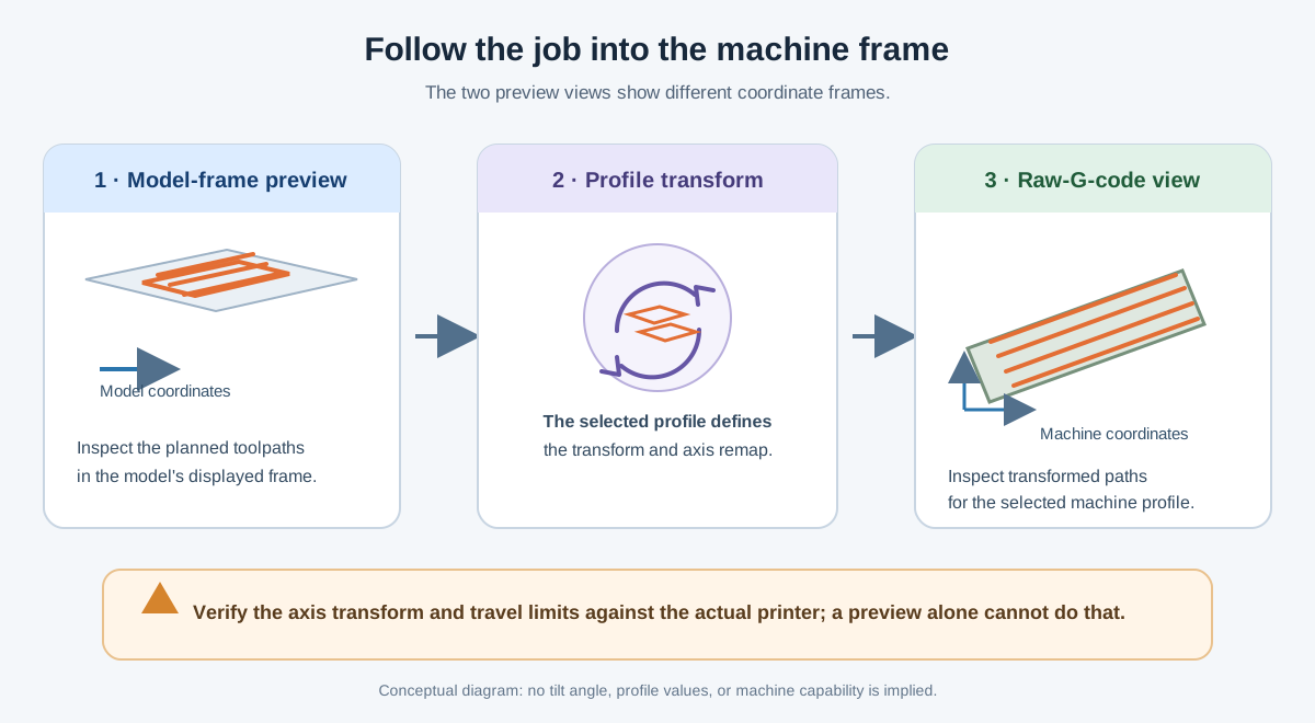
Machine-frame transforms affect where the toolhead is sent. OrcaSlicer’s documentation warns that incorrect values can exceed travel limits, and custom G-code is written without the slicer’s axis remap. Do not copy a transform or machine-code example to a different printer. If the profile or custom-code coordinates are uncertain, resolve that machine-specific question before relying on the generated output. Monitor an initial representative print as directed by the printer manufacturer.
Keep a belt-preflight record
Record the model revision and units; printer, firmware, and profile; OrcaSlicer build and belt-mode availability; belt width, tilt, and clearance; nozzle, material, and process; orientation and leading-edge observations; support, brim, and purge-space checks; transform and custom-code verification; and what the model and raw-G-code previews show. Mark unresolved values or untested outcomes explicitly. A slicer preview can expose path and coordinate issues, but it does not prove physical clearance, adhesion, support removal, dimensional fit, or print success.
For support topology, see support strategy for overhangs and bridges . For geometry checks before export, use model repair and sliced-preview preflight . For setup-specific feature fit, see thin walls, gaps, holes, and clearances .
Back to top ↑