A sagging bridge, curled overhang, broken support, or rough underside above support is a visible result, not a diagnosis. These features depend on geometry, toolpath classification, material, cooling, support contact, and the printer’s condition. Find the first place the print went wrong before changing global flow or motion settings.
Locate the first failed feature
Record the printer and variant, firmware, slicer and version, material and dry history, nozzle, plate, layer height, support type and interface, feature orientation, and the point where the defect begins. Photograph the failed region before removing strings or broken supports. If later layers contain spaghetti or a nozzle collision, use the earlier layers and the generated job to identify what failed first.
| What you see | First question | What it does not establish |
|---|---|---|
| Lines sag below a span | Is the region actually printed as a bridge, and what are its span, direction, and layer context? | That the whole print needs lower flow or a new motion setting. |
| An overhang edge curls or collapses | Did the unsupported edge deform before another part or nozzle hit it? | A universal overhang angle or cooling value. |
| A support tower detaches or breaks | Did its base adhere, did the tower remain stable, and did the toolpath reach the intended feature? | That every support warning predicts a failed print. |
| The underside above support is rough | Is the layer classified as a supported surface, bridge, or ordinary perimeter, and where is the interface? | That changing global extrusion will correct the contact geometry. |
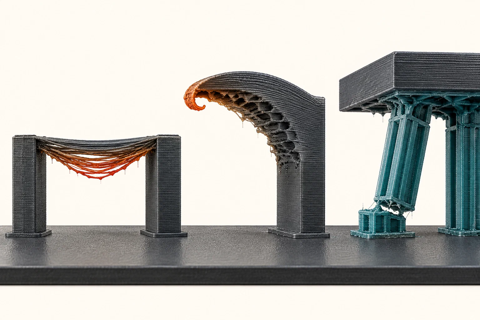
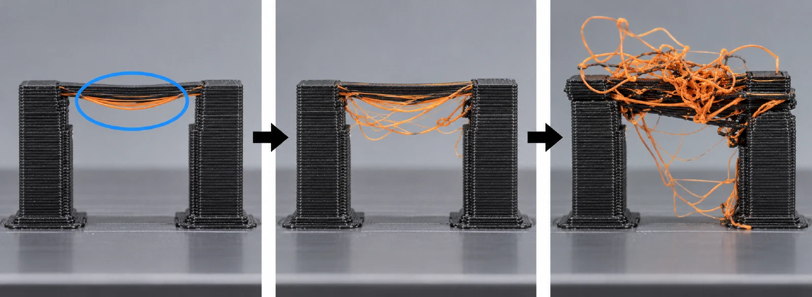
Similar-looking damage can begin earlier. A detached base belongs with first-layer diagnosis ; widespread thin or missing lines belong with under-extrusion diagnosis ; a displaced layer or collision belongs with motion and fault triage .
Inspect the model and generated path
Open the exact sliced file in the matching slicer version and inspect the affected layers. Confirm whether the span is treated as a bridge, whether support reaches the surface, and whether per-object or per-feature overrides change speed, cooling, or interface behavior. Check the orientation and whether a support island or a less demanding direction would change the geometry. A slicer preview shows intended paths; it cannot confirm actual extrusion, cooling, adhesion, or motion.
Manufacturer guidance treats these branches separately. Prusa’s bridging instructions discuss bridge-specific flow, speed, cooling, and geometry choices; its support guidance covers support stability and contact. The H2C manual gives its own overhang and support examples. These instructions describe their named products and workflows. Do not transfer their numeric examples, thresholds, or slicer controls to another printer, material, or software release. A warning in a preview is a prompt to inspect the feature, not proof that the print must fail.
Run one bounded experiment
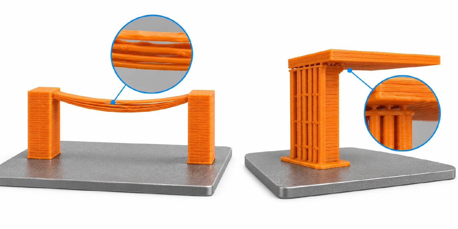
For a true bridge, use the exact printer and slicer’s documented bridge controls and change one relevant variable at a time. Keep material, nozzle, layer height, geometry, and the rest of the profile fixed. Compare the span for sag and continuity, and also check for weak bonding or a worse surface elsewhere. For a support failure, first verify the support path and attachment; then test one documented stability, contact, or geometry change. For a poor supported surface, inspect support interface and layer classification before adjusting global flow.
When the geometry itself is the main constraint, reorientation, splitting the model, or intentionally adding support may be more appropriate than tuning. Check the consequences for strength, surface finish, support removal, and print time. A design example for one printer does not set a universal angle or span limit.
Verify the feature that failed
Repeat a small representative bridge or support section with the same recorded setup. Inspect sag, line continuity, base attachment, support stability, and the surface above support. If it passes, confirm the relevant feature on the intended geometry before relying on the part. Stop if the printer scrapes, collides, shifts, or develops an earlier extrusion or adhesion failure. Preserve the failed sample and job file when the cause remains unclear, and use the matching manufacturer or slicer support path rather than compensating with unrelated settings.
Back to top ↑